An electrical inspection report is the document in which a qualified professional states, with measurements and evidence, what condition the installation is actually in. There are two kinds: one that gives problem, location, number and cost, and one that uses adjectives where readings should be. This guide covers what the standard demands and why the price moves so much between buildings.
I sign reports as an electrical technician, with an ART registered for the site location. Without that record the paperwork has no value to the body asking for it — and the ART is exactly what makes me legally answerable for every page.
When a report is mandatory
The obligation rarely comes from the installation; it comes from whoever requests the document. Before scoping a job I ask three questions: which body required it, for what purpose, and what validity period it accepts. Those answers change the inspection route, the level of detail and the deadline.
| Who asks | What they usually require | What I use as reference |
|---|---|---|
| Fire marshal | Inspection report covering wiring and lightning protection, to issue or renew the AVCB | NBR 5410, NBR 5419 and the state fire service technical instructions |
| Insurer | Electrical risk proven absent with recent insulation readings and thermography | Policy clauses plus NBR 5410 |
| Utility | Compliant service entrance, circuit identification and sometimes earthing tests | Access group requirements and PRODIST |
| Building manager or commercial lease | Board condition, phase balance and separation of common-area circuits | NBR 5410 and the lease contract |
| Court expert or client audit | Answered questions with photo, instrument and declared method | Civil procedure rules and the applicable standards |
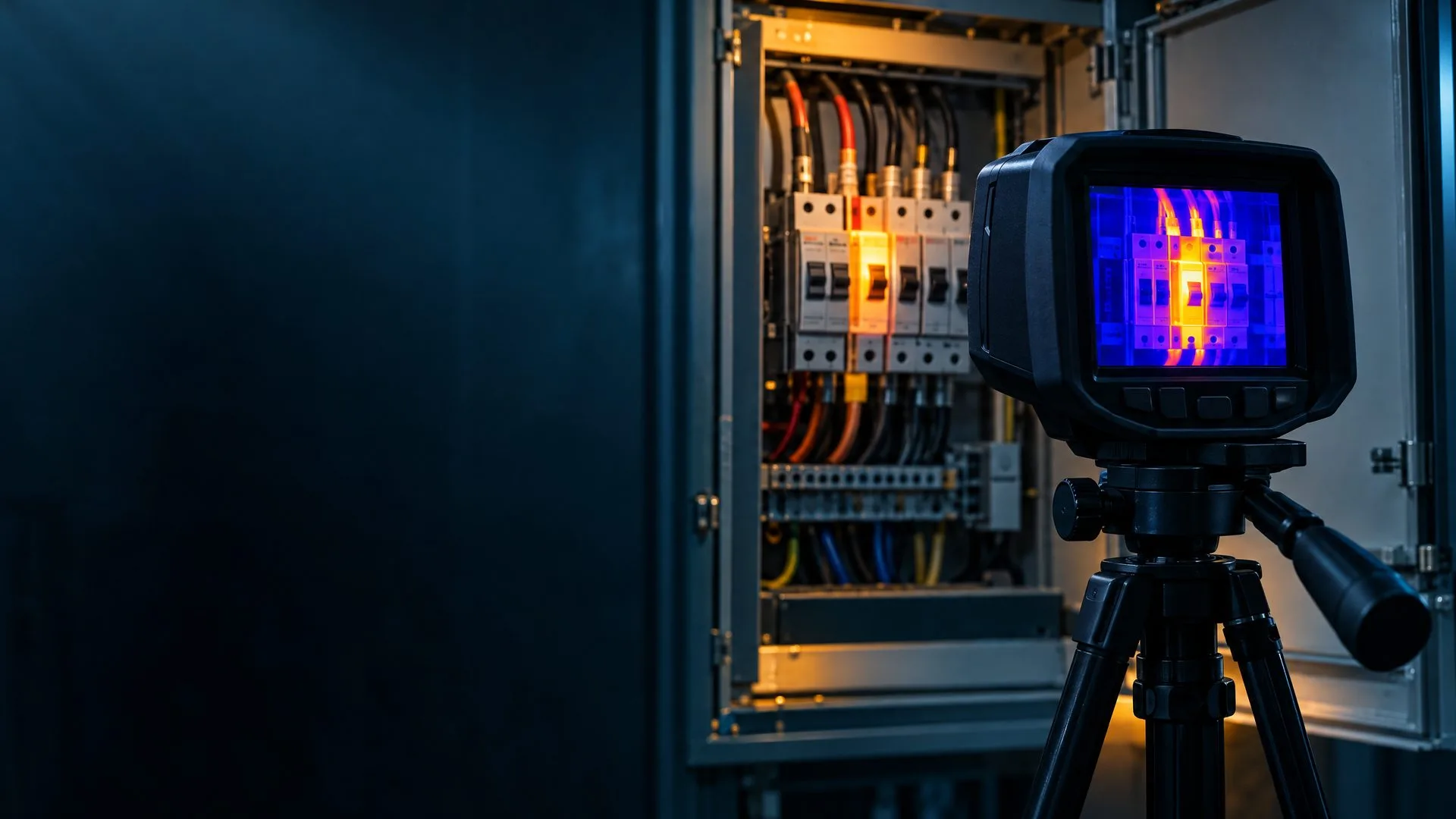
If the fire service is the requester, the report has to cover the lightning protection system whenever the building has one. If it is the insurer, thermography is what carries weight: the evidence that no connection is quietly overheating behind a busbar.
What is measured on site
A large share of the work is visual inspection, and it is the stage that fails most often: a well-built installation is recognisable before any instrument touches it.
- Circuit identification at the board and at the outlets, checked point by point against the diagram;
- Protection present and matched: breaker sized to the conductor, RCD where required, intact busbar;
- No splice outside a box, no patching, no conductor outside its conduit;
- Ingress protection consistent with the environment, plus barriers, board covers and clear access;
The tests and what each one answers
Each test answers a different question, which is why measuring insulation alone convinces nobody. Below are the tests I run and the conditions of each reading.
| Test | What it answers | How I measure |
|---|---|---|
| Continuity of protective conductors | Whether every exposed metal part has a real path back to PE | Ohmmeter or microhm meter, installation preferably de-energised |
| Insulation resistance | Whether insulation between live parts, and to earth, is intact | Megohmmeter, usually 500 V DC, circuit isolated and loads disconnected |
| Fault current | How much current leaks to the enclosure under normal operation | Leakage clamp, energised circuit under load |
| Earth-fault loop impedance (Zs) | Whether the protective device opens within the maximum allowed time | Loop tester, energised, compared against NBR 5410 limits |
| RCD trip | Whether the device opens at its rated current and time | Residual current injection with a dedicated instrument |
| Thermography | Where a loose connection, imbalance or overload is heating up | Thermal camera with the circuit carrying representative load |
| Earthing and lightning protection | Whether mesh, down conductors and bonding match the design | Earth tester and dimensional check against NBR 5419 |
Two habits separate a properly executed test from a shop-window number: recording the conditions of the measurement — temperature, circuit load, humidity — and repeating the reading. Insulation moves with humidity, and thermography with no load shows nothing.
Which standards I apply
The report must cite the basis of every requirement. Without that, a flagged item stops being a conformity question and becomes the technician's opinion.
| Document | Role in the report |
|---|---|
| NBR 5410 | Low voltage: load forecast, sizing, protection, discrimination and final verification |
| NBR 5419 | Lightning protection: air terminals, down conductors, mesh and bonding |
| NBR 14039 | Medium voltage, where the site owns a substation or switchgear |
| NR-10 | Safety in electrical work: records, de-energisation, qualification and training |
| NR-35 | Work at height, for roof, riser or elevated structure access |
| State fire service technical instructions | Format accepted for the AVCB and compliance certificate |
The withdrawn NBR 5413 still turns up in checklists copied from memory. If you receive a report resting on it, ask which instrument produced each line.
What it costs and what moves the price
There is no honest price list for an electrical report: what you pay for is field time and technical liability. I quote a fixed scope, never an hourly rate, and the scope moves with six factors.
- Number of boards and tested circuits — the heaviest factor, since each circuit is one measurement and one photo record;
- Whether de-energisation is needed: a short shutdown window multiplies field time;
- Thermography charged per circuit scanned, with or without a temperature report;
- Height and classified areas, which require NR-35 compliance and a permit to work;
- Missing drawings: rebuilding information in the field is unbilled hours;
- Travel, urgency, the ART, and the time to write the report and the correction schedule.
Typical lead time, from booking to PDF
For installation and lightning protection reports of small and medium size, the document is ready about 5 business days after the survey. Thermography across several hundred circuits can reach 10 business days. Before promising a date to a public body, add the filing time, not only the drafting time.
Failures that most often stop an approval
- Board with unidentified circuits, or labels that do not match reality;
- Neutral and PE bridged where separation is required, defeating the RCD;
- Breaker oversized for the conductor: the cable heats before the breaker trips;
- Missing RCD in wet areas, outdoor outlets and every circuit NBR 5410 requires it;
- Down conductor interrupted, poorly spliced or crossing a wall without mechanical protection;
- Improvised earth electrode with no measurement proving an acceptable resistance in that soil;
- Thermography performed with no load, which proves nothing and leaves the risk open;
- Generic report: no photo, no instrument named, no measurement date.
A good report is not one that finds no problem. It is one that finds the problem with an address, a number, a risk level and a cost — because that is all that lets you decide and execute.
What arrives with the report
Besides the signed PDF and the ART, you get the non-conformity schedule with risk, deadline and estimated cost, the photo record with locations, the thermography report and the list of instruments used in each test.
When the defect is a design problem rather than a maintenance one, the route changes: the board needs rebuilding or the installation a full review, which the electrical design page covers. The FAQ answers the questions I receive most, and the quote form comes back within 4 business hours.
What to take away
- The requirement comes from whoever asks for the document — fire marshal, insurer, utility, building manager or court — and each accepts a different scope.
- Four tests are the core: PE continuity, insulation resistance, fault current and protective device verification; thermography reveals the defect hidden under load.
- Price follows circuit count, de-energisation windows and height access, not the building's floor area.
- A report without a measurement date, named instrument and photo is worth little at inspection.
- A flagged fix that is never re-inspected leaves the risk open and the policy weakened.
Technical lead
Julio C. Fornazier
Leading Energia Criativa, Julio signs low and medium voltage electrical designs, technical inspection reports and energy efficiency plans for industrial, commercial, condominium and residential clients across Brazil. His method is simple: measure before specifying, simplify the circuit, cut waste and deliver the full documentation needed for utility approval, fire marshal audits and inspections.